Mounting and structural considerations for LED displays: weight, wind and walls
An LED wall is a structural element, not a screen. Here's how to size structure, choose mounting type and avoid the three failure modes we see most often.
Most LED-wall sales conversations focus on the screen — pitch, brightness, refresh rate. The structure that holds it up gets a passing line in the install quote and almost no engineering scrutiny.
That’s a problem because the structure is where almost all real-world LED-wall failures originate. Cabinets fall off walls. Frames flex enough to crack solder joints on the inside. Wind loads underestimated by a factor of two pop a billboard off its mast in a single storm. The screen doesn’t fail — the engineering around it does.
Here is what to think about, in the order you should think about it.
1. Weight
LED cabinets are heavier than they look. A typical 500 × 500 mm indoor P2.5 cabinet weighs 8–12 kg. A 600 × 337.5 mm outdoor P5 cabinet weighs 14–20 kg. A 1 m × 1 m outdoor P10 unit can hit 35 kg.
For a 4 m × 2.5 m indoor P2.5 wall, that’s 40 cabinets at ~10 kg each = 400 kg of cabinet plus ~80 kg of frame and rigging = ~480 kg dead load hanging on a wall.
A standard plasterboard partition is rated for about 30 kg/m² of distributed load and dramatically less point-load. You cannot hang 480 kg on it. Either you mount to the structural slab/wall behind, or you build a free-standing frame and the LED wall presents to the partition.
What to check before signing: the dead weight of the proposed cabinet × the array size, and a written engineering opinion from your builder or structural engineer that the host structure can carry it.
2. Wind (outdoor only)
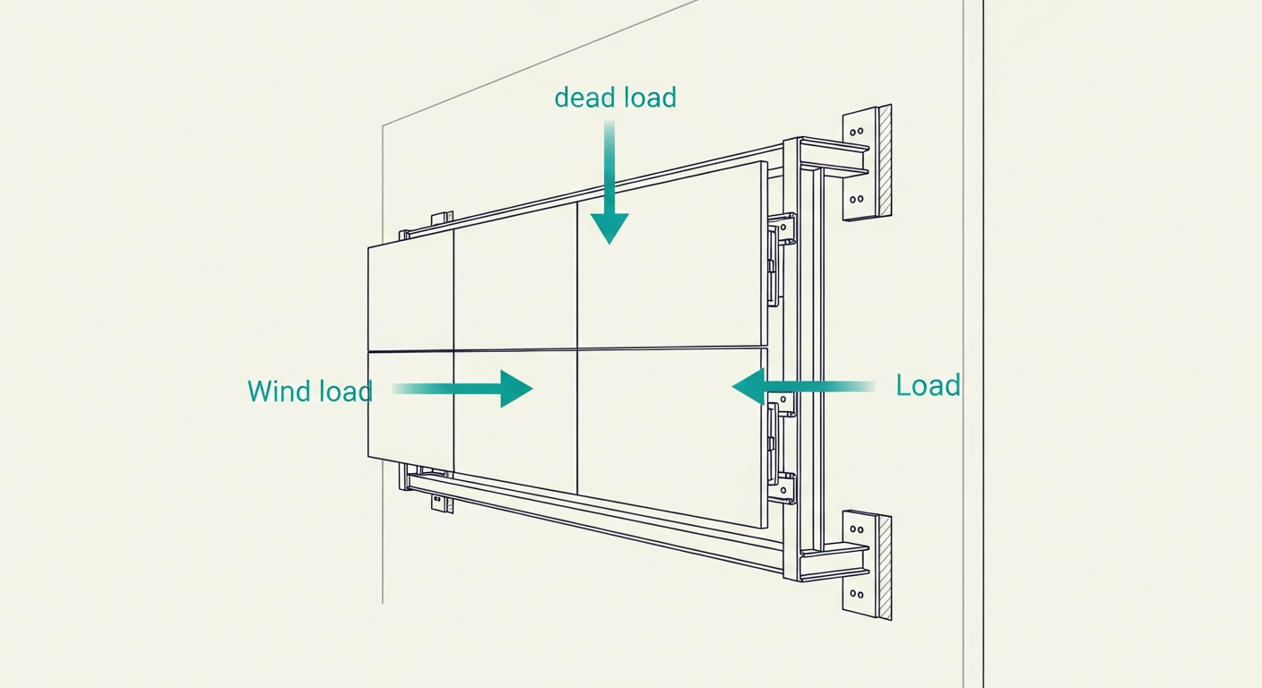
For outdoor installs, wind load almost always exceeds dead load as the design case.
The relevant standard is AS/NZS 1170.2 (Structural design actions — Part 2: Wind actions). It defines a region-specific design wind speed (Region A1–C, with NSW/VIC mostly A2–B and far-northern WA/QLD in C/D), a terrain category (urban vs open vs coastal exposure) and an importance level (which determines the return period — 500 to 2,500 years for typical commercial signage).
A worked example. A 6 m × 4 m billboard in Sydney (Region A2, terrain category 2.5):
- Design wind speed (500-year return): ~45 m/s.
- Dynamic pressure: ~1.2 kPa.
- Drag coefficient on a flat sign: ~1.2.
- Design wind load on the face: ~35 kN — about 3.5 tonnes of horizontal force.
Multiply by the lever arm to the base attachment point and the moment becomes very large. A 6 m × 4 m billboard on a 4 m mast has a design overturning moment of ~150 kN·m. The mast, base plate and footing must all carry this.
For coastal NSW, far-north QLD or any cyclone-region site, wind load can double or triple.
What to check: is there a stamped wind-loading certificate from a registered structural engineer for your specific cabinet array, frame and host structure? Generic “passes AS/NZS 1170.2” without site-specific calculations is not a certificate.
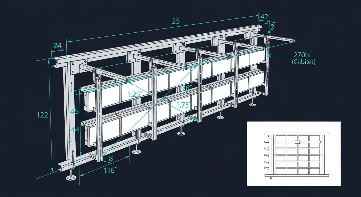
3. Frame deflection and “racking”
Even an indoor wall flexes. When mounted to a partition wall or back-of-house steelwork, the frame takes some of the cabinet array’s dead weight via cantilever moments. If the frame is under-spec’d, it deflects.
The visible result: thin shadow lines between cabinet rows that vary across the wall (worse near the edges, less in the middle). The invisible result: cyclic stress on solder joints inside the cabinet from temperature-driven micro-flex, leading to dead pixels at solder failures three to five years in.
For walls above 3 m × 3 m we strongly recommend an aluminium box-section frame engineered to deflect less than L/360 (i.e. less than 8 mm at 3 m span) under cabinet dead-load. Cheap brackets that bolt cabinets directly to plasterboard or to a single piece of channel will deflect 20–30 mm and you’ll see it.
4. Service access
A wall is only as maintainable as the access plan around it. Three modes:
- Front-service. Modules pop out from the front. No rear access required. Mandatory for any wall mounted hard against a building structure or set into a wall recess.
- Rear-service. Modules accessed from behind. Cheaper cabinets, but requires 800–1,000 mm of clearance behind the wall — often unavailable.
- Hybrid. Modules front-service, PSU and receiving cards rear-service. Practical compromise for free-standing walls.
Specify front-service for any wall set into a building. The 30% capital premium pays back many times over the asset life in service-call costs.
5. Power and signal cable routing
The cabinet array needs power and signal entries. For most installs:
- Power: 32A or 40A 3-phase per ~25 cabinets, dedicated circuit, RCD-protected, isolator within sight of the wall.
- Signal: Cat6A from controller to first cabinet; cabinets daisy-chain after.
- Earth: Equipotential bond from frame to building earth, plus per-cabinet earth-return through power feed.
Run cables in the frame, not through the cabinet array. Cabinet-internal cabling should be supplier-provided pre-made; site-made cable is a frequent source of intermittent faults.
The three failures we see most
- Under-frame on partition walls. Plasterboard cracks, sometimes 6–18 months after install. The wall stays up because the cabinets are also resting on a floor lip, but the warranty void follows.
- Mast under-engineered for AS/NZS 1170.2. Outdoor billboard tilts or pops off in a once-per-decade storm. Insurer may decline.
- Generic spec-sheet hardware on coastal sites. 12 months of salt-air on standard fasteners and you have brown rust streaks down a $200,000 wall.
All three are avoidable with engineering done up-front.
Talk to us about your specific install — we’ll do a free preliminary structural sanity-check and flag if your proposed approach needs more engineering before it gets to a real quote.
Ready to move forward?
Got a project to spec?
Send us your venue, wall size and conditions — we'll come back with a tailored configuration and budget price.